Bolted connections are the foundation of modern mechanics and construction. The integrity of a huge metal structure, the safety of a car or the stability of industrial equipment can depend on the reliability of a single bolt. However, the choice of fasteners cannot be based on intuition. An engineer needs accuratecalculation of bolted joints, which takes into account all acting forces, material properties and operating conditions.
In this article, we will analyze the physics of the process in detail, consider the keybolted joint calculation formulasand learn how to use reference tables to select the optimal fastener.
Classification of bolted joints and types of loads
Before we get into the numbers, it's important to understand how a connection works. A bolt in a structure is rarely at rest—it's subject to various forces.
There are two main types of load that determine the calculation method:
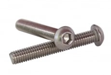
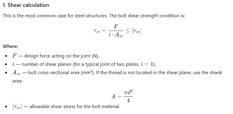
- Shear load (shear).The force acts perpendicular to the axis of the bolt. Example: joining sheets of metal together. Here the bolt acts as a pin, preventing the parts from slipping.
- Tensile load.The force acts along the axis of the bolt, trying to break it. Example: fastening pipeline flanges or suspending a load.
There are also combined loads, but for a basic understanding we will focus on these two as they are the basis for most engineering problems.
Basic formulas for calculating bolted joints
Engineering calculation is based on checking the strength condition: the stresses arising in the material under load must not exceed permissible values. Let's consider the scenarios in more detail.
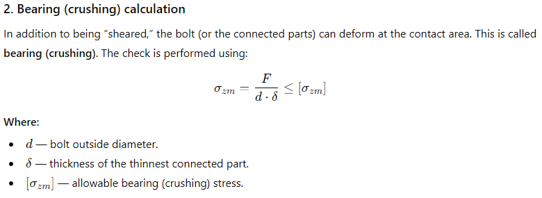
.png)
Bolt strength classes: how to choose the right one
Choosing a formula is only half the battle. The key parameter is the bolt material. Modern engineering uses a system of strength classes (e.g. 4.6, 5.8, 8.8, 10.9, 12.9).
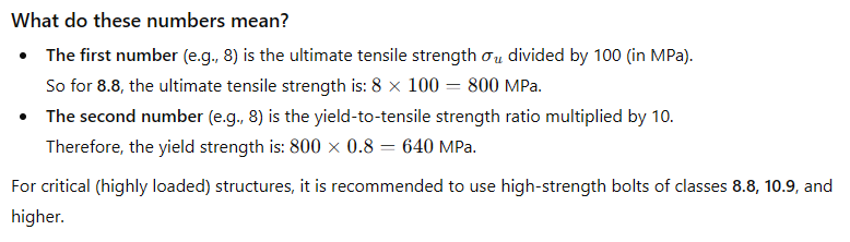
For critical structures (highly loaded), it is recommended to use high-strength bolts of classes 8.8, 10.9 and higher.
Bolted connection calculation tables and reference data
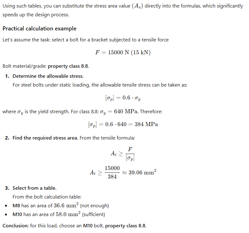
For quick selection of fasteners, engineers often use ready-madebolted connection calculation tables, which contain already calculated cross-sectional areas and allowable loads for standard threads.
Here is an example of a simplified table of geometric characteristics for metric threads:
|
Nominal thread diameter (d), mm |
Thread pitch (P), mm |
Internal thread diameter (d3), mm |
Estimated cross-sectional area (As), mm² |
|
M6 |
1.0 |
4.77 |
20.1 |
|
M8 |
1.25 |
6.47 |
36.6 |
|
M10 |
1.5 |
8.16 |
58.0 |
|
M12 |
1.75 |
9.85 |
84.3 |
|
M16 |
2.0 |
13.55 |
157 |
|
M20 |
2.5 |
16.93 |
245 |
|
M24 |
3.0 |
20.32 |
353 |
Typical errors in node design
Even with the correct formulas, you can make mistakes that will lead to destruction:
- Ignoring pre-tension. Most bolts only work effectively when they are tightened to a certain torque. This creates a frictional force between the parts that relieves the bolt shaft itself of shear forces.
- Using bolts of different strengths. In one connection, all bolts must be of the same strength class.
- Insufficient distance to the edge of the part. If the bolt hole is too close to the edge of the sheet, the material of the part itself may chip, even if the bolt holds.
Proper calculation of bolted joints is the key to the durability and safety of any structure. Understanding the physics of the process, the correct application of formulas and the ability to use reference tables allows engineers to create optimized and reliable assemblies. Remember that for critical structures, you should always be guided by the current state standards (DSTU, Eurocode) and conduct verification calculations taking into account safety factors.
Frequently Asked Questions (F.A.Q.) about bolted connection calculations
1. How to choose the correct bolt diameter for a flange connection?
Diameter selection bolt (studs) depends on two main parameters: the nominal diameter of the pipeline and the nominal pressure of the system. For standard flanges use tables for calculating bolted connections (for example, according to DSTU/GOST), not formulas. That is, for a flange of DU 100, an M16 bolt (8 pcs.) is required. Using a larger diameter than provided for by the standard will not increase strength, but may complicate installation.
2. What bolt strength class is required for flanges?
For flange connections operating under pressure (especially in Ukraine), bolts (studs) of strength class 5.8 or 8.8 are usually used. A higher strength class (for example, 10.9) is required for high-temperature, critical or highly loaded structures.
3. What is "pre-tension" and why is it needed in calculations?
Pretension is the force created when tightening the bolt (torque). It is necessary to seal the joint (in the case of flanges) and to provide friction between the parts being joined. This is taken into account in the calculations through the tightening factor so that external loading does not cause the joint to "open". This is critically important because with proper tensioning, the main shear load is taken by friction, not the bolt shaft.
4. How to properly tighten flange bolts to avoid damage?
Tightening should be done sequentially, "crosswise" and in several stages (usually 3-4 passes). This ensures an even distribution of the load on the gasket and prevents the flanges from skewing, which can lead to leaks. It is recommended to use a torque wrench to control the tightening torque, as excessive force can lead to the flow of the bolt material or damage the gasket.